
Splines originally developed for shipbuilding. Needed a way to draw a smooth curve through a set of points. Solution - place metal weights at points and pass a thin wooden beam (spline) between weights. Beam will adopt minimum energy position with respect to metal weights:

Influence of each weight is maximum at point of contact, and decreases smoothly away from that point.
Problem of data exchange. Need an exact mathematical representation that also has good design properties (smoothness, ease of control etc.)
Polynomial curves are good for this:
a + bx + cx^2 + dx^3 + ...
Extended to B-splines (Basis splines) - a sum of lower level polynomial splines, then to NURBS:

NURBS are a superset of conics, splines, Beziers. They are parametric polynomial curves.
Parametric vs Implicit polynomials
For 2d geometry, need x and y positions:
Implicit, eg
ax^3 + by^2 + 2cxy + 2dx + 2ey + f = 0
Requires solving equation to evaluate points on geometry.
Parametric eg
x = a + bt + ct^2 + dt^3 + ...
y = g + ht + jt^2 + kt^3 + ...
Easier to evaluate.
Highest polynomial term t^2 - quadratic, degree 2
Highest polynomial term t^3 - cubic, degree 3
A NURBS curve is a composite curve, a collection of individual curve segments joined at knot values:
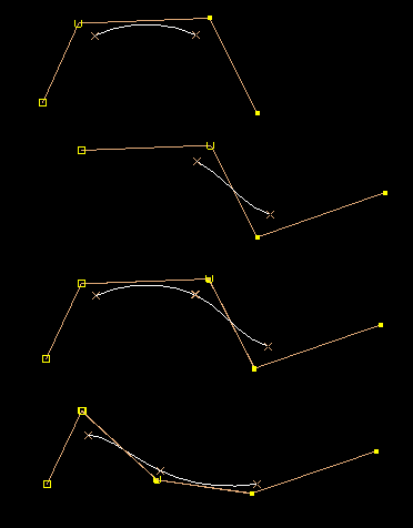
Have local control, a given CV influences a limited range of the total composite curve.
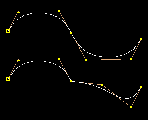
Bezier segments
 /
/
Bezier curves can be represented as joining NURBS curves with multiple end knots, or a single NURBS curve with multiple interioir knots. Enforcing tangency is hard because the relevant CVs need to be aligned by external constraints.
Closed and periodic NURBS curves - overlap uniform or multiple end CVs: The ends are no different from joins of individual spans:
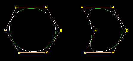
Periodic curves have uniform end knots which overlap, producing the same continuity as in the interior of the curve. The seam is no different from any other knot on the curve, so moving CVs in the region of the seam will cause deformations that retain the smoothness of the curve.
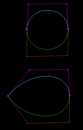
Closed curves touch, but are not guaranteed to have any greater continuity, ie tangent continity. This is the same as any curve with multiple interior knots.
Subsetting geometry
For cubic curves, 1 CV affects 4 spans, and 4 CVs define 1 span completely. For bicubic surfaces, 1 CV affects 16 patches, and 16 CVs define one patch completely.
Because a curve or surface is a collection of segments or patches joined together with automatic continuity, one can easily extract subregions:
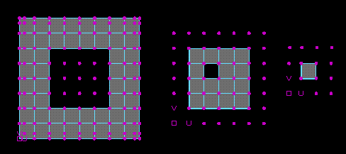
In the above, the middle surface is extracted from the left surface by simply copying all the CVs that define the patches in the middle surface. The subset of knots in U and V is also copied from the left surface. Similarly, the right surface is obtained by copying the required CVs and knots from the middle surface. (Note - each surface will exactly fit into the hole in the surface to its left - the fact that they do not appear to is an optical illusion.)
The degree is the highest power of the polynomials that define the spline.
Which degree to use?
For planar surfaces, use degree 1 (or even better polys) wherever possible for max speed and memory efficiency, esp if 1000s of surfaces. A degree 1 plane with 1x1 patch consumes 4x less memory than a single patch degree 3 surface.
Knots hard to visualize because they exist only in parameter space. They are the parameter values at which curve segments join.
One way to think of them is as fixed points on an rubber band or sheet, so although their positions move in 3d space they stay in the same relative position on the curve or surface.
The 3d position of the knot points is affected by changes in the CV positions. The 3d positions of the curve or surface at knot values are called Edit Points
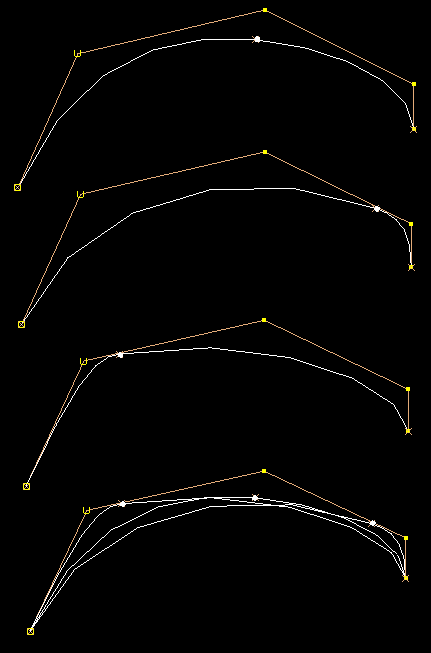
White dots mark edit points.
In theory modelling using edit points is more intuitive and easier than using CVs, because EPs sit directly on the curve. In practice, there are problems:
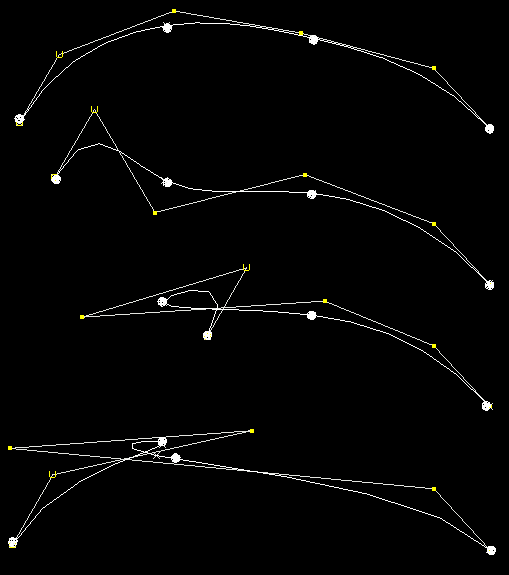
This curve has 6 CVs and 4 EPs. EPs are marked as large white spheres.
Moving EPs is not particularly recommended, particularly if moving them large distances. Behaviour is not intuitive, and can generate bad geometry.
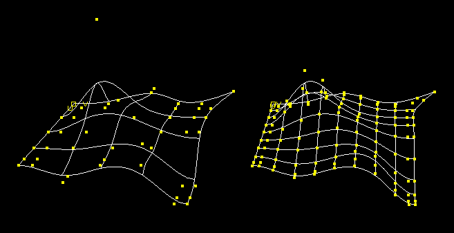
One knot inserted halfway between each existing knot in U and V in the surface at the left, to produce the right surface, which has exactly the same shape as the left one but twice the number of patches in each direction.
For a surface, knot insertion and isoparm insertion are the same, since isoparms are defined as lines on surface at the knot positions.
Can always insert any number of isoparms/knots and preserve shape exactly. This is intuitively obvious, and is the basis for refinement schemes.
Knot/isoparm removal ususally involves approximation, for obvious reasons.
Ideally the user would be insulated from the surface representation. This is not the case for NURBS.
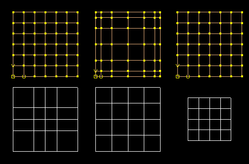
Above are three surfaces (in white) with the corresponding CVs and hulls shown above each surface:
We usually use the second of these in Maya.
In some ways the third is best. It provides an even parameterization with even knots, and allows easy joining of adjacent surfaces by simply overlapping (degree) rows of CVs (in exactly the same way as adjacent patches are joined within a single NURBS surface.) (See example .)
The same principle applies to curves, but is harder to illustrate. This means placing CVs equally does not give the best curve in terms of even parameter distribution, unless it also has non-multiple end knots.
Scaling all knots values has no effect on the appearance of the geometry (it does affect the magnitudes of the parametric derivatives though.)
One normally like smoothly parameterised geometry. Some tools work in parameter space, so the smoother the parameter distribution the better the results are likely to be. However a uniform parameter distribution is not the same as uniform sizes curve segments or surface patches. For an example see the next section:
Chord length knots. This means the parameter value of the knots scales directly with the distance along the curve between knots.
In general cannot get an exact chord length mapping on a curve if the curve is created using CVs! This is because the 3d positions of the knots (EPs) are only known once the curve has been created, so one needs to have the curve before assigning parameter values to the knots. However, assigning parameter values to the knots changes the shape of the curve. Thus there is a circularity. Possible solutions:
We use the second of these approaches.
Chord Length mapping is not maintained once the user starts to edit the curve by moving CVs. Instead the knot values are locked. To allow the knots to recompute would in theory give the most satisfactory curve for the current CV positions, but would potentially cause unexpected shape changes, and may cause jumps in the shape of the curve if the curve was actually not exactly chord length parameterised to begin with.
Users have asked for -chordLength flag - this cannot be provided since, as can be seen above, the implementation of "chord length" mapping is not unique.
The following two images show the difference between uniform and chord length mapping:
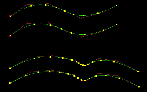
Using Edit Points for chord length curve creation gives better results:
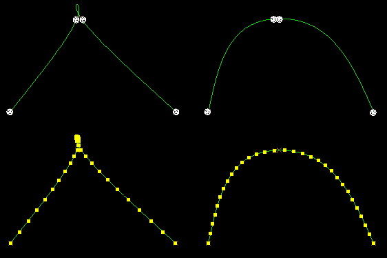
In this case the chord length option produces a very good result. This is not surprising, since the EP positions are defined in advance. It is still not exactly chord length, since the straight-line distance between EPs is used to define parameter rather than the distance along the curve (which is not known at that time), but it is clearly close to a true chord length mapping.
Imagine Uniform parameterization is like having a rubber band at rest and marking equally spaced points along the band, then deforming the band. Using this analogy, Chord Length mapping would be stretching the band into the required shape, and then marking equally spaced points along this shape. Such a parameterization is clearly smoother in general.
So to create a chord length curve, it is best to use Edit Points. However if a curve is to be edited, it is better to use CVs to create the curve, to avoid the unexpected shape changes that may happen with curves created using EPs.
Uniform does not mean equally sized patches
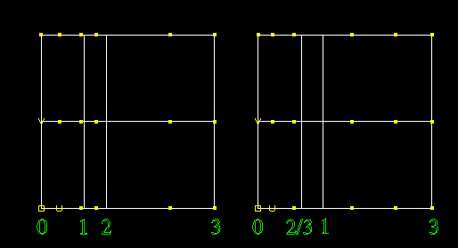
The above surfaces look the same, although one has uniform knots and the other has chord length knots. "Uniform" refers to the parameter space representation, not the world space representation.
NURBS is a bad name - strictly it excludes uniform and nonrational cases.
What are they? Unfortunately this term is used in two different ways:
Therefore is a surface is displayed at high resolution with many 'isoparms' of the first type visible, only the subset of these that correspond to the second defintion of isoparms can actually be deleted.
Nonrational geometry is a sum of polynomials. Rational geometry is a ratio of sums of polynomials. At a result they are considerably more complex mathematically. The main advantage of rational geometry is that they can generate exact conice - arcs, circles and spheres. The default Maya (nonrational) circle and sphere are not exactly spherical, although they are pretty close:
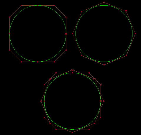
As can be seen, there is not much difference between the rational and nonrational cases, and it is always possible to increase the number of spans on the nonrational case to get even better accuracy. Rational geometry is really only needed for precision CAD work.
Rational circles and spheres have multiple knots, which is ugly for editing since the surface will lose continuity if certain CVs are moved. Note that rational geometry does not automatically mean the geometry will lose smoothness when deformed - it just happens to be true for the circle and sphere primitives created using rationals, since they are composed of multiple Bezier patches.
Very few places in Maya generate rational geometry (only offsetCurve & bevel) although all nodes handle it.
The only way to create rational geometry from scratch is to import it or to edit weights using the setAttr command (see next section.)
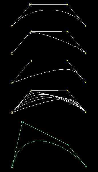
Effect of varying weights on a CV:
Setting weights must be done using the setAttr command, for example:
setAttr curve1.wt[2] 2.5;
in Maya.
So weights do provide additional freedom for manipulating surfaces, but generally not very useful freedom. There is not much demand from animation customers for weight editing.
Negative weights Maya, Studio and most systems do not allow them. One major problem with negative weights is that they break the convex hull rule which states that the curve always lies within a region that is shrinkwrapped to the CVs (the hatched region below):
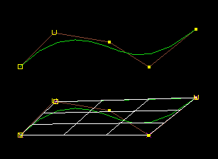
The convex hull rule makes certain types of geometry operation much faster (eg intersections, display culling) because it is possible to compare the hulls rather than the geometry itself as a fast way to see if objects may intersect with each other. If the convex hulls do not intersect, then the geometry cannot intersect either.
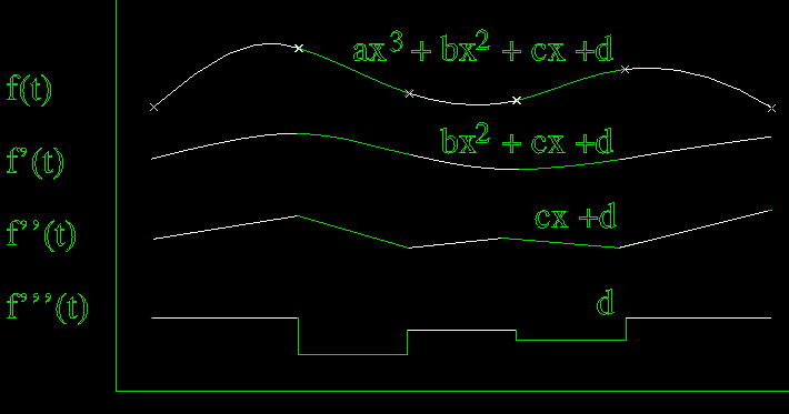
The derivative of a NURBS is also a NURBS, of degree lower by 1.
The continuity at each segment join is (degree-1), so a cubic curve has two continuous derivatives.
Multiple knots remove levels of continuity at knots, while maintaining the original smoothness between knots:
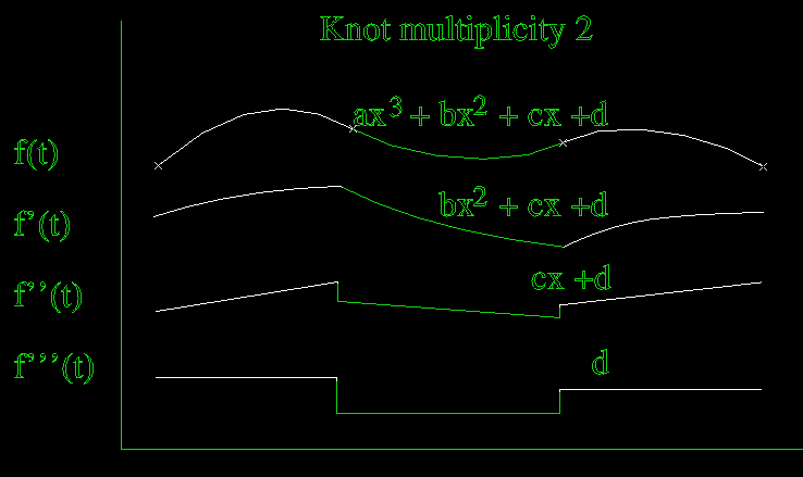
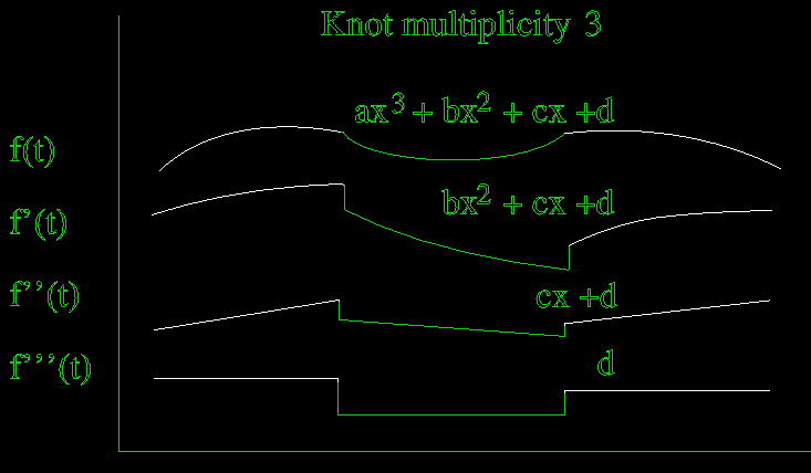
A multiplicity of (degree) acts as a Bezier (ie no tangency between adjacent segments).
A multiplicity value greater than the degree is allowable in theory, and would in fact cause the curve to break in two. However such cases are not allowed in Maya.
There is no way to edit knot values explicitly in the UI, need to save and edit the ASCII file. Knots can be defined when a curve or surface is first created though.
Multiple CVs act similarly to multiple knots (although mathematically they are different.)
Parametric and geometric continuity
Geometric continuity (Gn) - is smooth in 3d space.
Parametric continuity (Cn) - is smooth in parameter space.
Notation - G
Normally curves with Cn continuity also have Gn continuity, but it is not necessarily always the case. By having multiple CVs at the same location in 3d space, it is possible to have a curve that is tangent continuous parametrically (C1) but has a sharp corner, so is not tangent continuous in 3d space (G1).
Benefit of C over G? Mathematically better behaved. To the user, they appear identical.
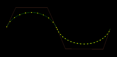
If the above curves were moved to touch, they would join with at least tangent continuity in 3d space, but the rate of change of parameter would be discontinuous at the join, so it would be at least G1 (possibly G2) but not C1.
Can consider parameter variation as equivalent to the speed of a point moving along the curve, passing equal parameter distances in equal time. Then loops in the curves can be thought of as 'overshoots' where the parameter is moving too fast to slow down and go around a sharp corner.
Most tools give G continuity (eg stitch, align.)
Multiple knots/CVs are generally bad for smooth geometry. Can look smooth until deformed (eg rational circle.) Some tools create results with multiple interior knots, so the results may not be suitable for editing.
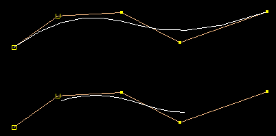
The above two curves have the same CVs and interior knots, the first has multiple end knots while the second has uniform end knots.
Advantages of Multiple end knots
Advantages of Uniform end knots
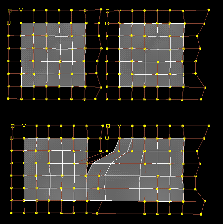
Note - joining surfaces by snapping CVs is not always as easy as it seems:
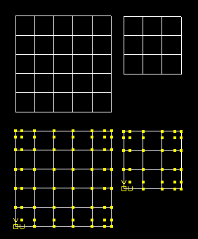
Extra row of CVs at edges of surfaces can cause problems, since there is nothing for them to snap to. In the above case, the smaller surface has a horizontal row of CVs one from the bottom edge that do not have corresponding CVs on the larger surface.
Move CV Normal - normal to what? Closest pt? Edit pt?
Cannot trim across the seam.
Cannot join trimmed surfaces, since parameteric derivatives are only available
in u and v.
Deformers break Objects made of multiple surfaces can come apart
when deformed, for example by lattices. This is especially noticable with
trimmed surfaces, but can happen with untrimmed surfaces too.